Terrario-elettronico: Difference between revisions
No edit summary |
|||
| (26 intermediate revisions by the same user not shown) | |||
| Line 14: | Line 14: | ||
''"[...] Mari ha ragione, tutti devono progettare: in fondo è il modo migliore per evitare di essere progettati." ''<ref>[https://syllabus.pirate.care/library/Enzo%20Mari/Autoprogettazione_%20(221)/Autoprogettazione_%20-%20Enzo%20Mari.pdf]Valutazione critico-artistica | ''"[...] Mari ha ragione, tutti devono progettare: in fondo è il modo migliore per evitare di essere progettati." ''<ref>[https://syllabus.pirate.care/library/Enzo%20Mari/Autoprogettazione_%20(221)/Autoprogettazione_%20-%20Enzo%20Mari.pdf]Valutazione critico-artistica | ||
(G.C. Argan, in «L'Espresso», 5 maggio 1974)</ref> | (G.C. Argan, in «L'Espresso», 5 maggio 1974)</ref> | ||
=== Workshop zine === | |||
The days following the workshop have been devoted to the design of a zine/manual that could serve as a record of the laboratory, ultimately being the offline version of this very page. <br> | |||
Together with Flora and Pongie we thought of a foldable format that could fit inside the synth's case, aligning with its screw holes. [https://habitattt.it/wiki/images/1/1b/Terrario_elettronico_-_A3_zine.pdf Download it here], then print it, trim it, fold it, punch it. | |||
=== Basic theory on electronic components === | === Basic theory on electronic components === | ||
'''TRANSISTOR''' <br> | '''TRANSISTOR''' <br> | ||
The heart of the synth and semiconductor electronics in general. It usually amplifies a small signal thanks to a | The heart of the synth and semiconductor electronics in general. It usually amplifies a small signal thanks to a DC current supply, but this time it has been forced to work in its avalanche breakdown region, emitting current pulses at rhythmic intervals. We use S9018 transistors for their ability to oscillate at very low voltages so that a simple 9V battery is enough.<br> | ||
[[File:T E transistor.png|frameless]]<br> | |||
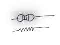
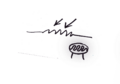
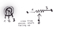
'''RESISTOR'''<br> | '''RESISTOR'''<br> | ||
A passive component that resist the flow of the current – it can have different forms: | A passive component that resist the flow of the current – it can have different forms: | ||
*'''FIXED RESISTOR''', with a set value expressed in Ohms; | *'''FIXED RESISTOR''', with a set value expressed in Ohms; | ||
*'''LDR or PHOTOCELL''', a sensor that features more or less resistance through its path whether it is exposed to sources of light; | *'''LDR or PHOTOCELL''', a sensor that features more or less resistance through its path whether it is exposed to sources of light; | ||
*'''POTENTIOMETER''', a variable resistor controllable by turning a knob – it can be wired in different ways to achieve different results. | *'''POTENTIOMETER''', a variable resistor controllable by turning a knob – it can be wired in different ways to achieve different results. | ||
<gallery> | |||
T E resistor.png|FIXED RESISTOR | |||
T E ldr.png|LDR | |||
T E pot.png|POTENTIOMETER | |||
</gallery> | |||
'''CAPACITOR'''<br> | '''CAPACITOR'''<br> | ||
A sort of small battery that can store electricity and discharge at a set rate. It also can be used to block DC current and let AC pass through. There are many different types of capacitors, but pay special attention to electrolytic ones: those are polarized components that need to be oriented in a specific way (negative pole towards the lower potential side). | A sort of small battery that can store electricity and discharge at a set rate. It also can be used to block DC current and let AC pass through. There are many different types of capacitors, but pay special attention to electrolytic ones: those are polarized components that need to be oriented in a specific way (negative pole towards the lower potential side).<br> | ||
[[File:T E cap.png|frameless|frameless]]<br> | |||
'''LED'''<br> | '''LED'''<br> | ||
A light emitting diode, here used as a load for the circuit: each time the transistor emits an audible pulse, the LED flashes in sync. LEDs | A light emitting diode, here used as a load for the circuit: each time the transistor emits an audible pulse, the LED flashes in sync. LEDs are polarized components: always orient the cathode aka shorter leg aka minus sign towards ground.<br> | ||
[[File:T E led.png|frameless|frameless]]<br> | |||
=== How the circuit works === | |||
The circuit is based around 2 oscillators, wired in parallel, that emit pulses at various frequencies, from percussive thumping all the way to the audible range.<br> | |||
[[File:T E block diagram.png|left]] | |||
We can tweak and mix and contaminate the relations between these 2 oscillators, even having them interact with light sources. This project features a series of interfaces to achieve this, but the combinations are endless: | We can tweak and mix and contaminate the relations between these 2 oscillators, even having them interact with light sources. This project features a series of interfaces to achieve this, but the combinations are endless: | ||
*OSC1 pitch control via a potentiometer | *OSC1 pitch control via a potentiometer | ||
| Line 41: | Line 53: | ||
*OSC1 output volume control via LDR (the effect is a kind of VCA, you can get interesting side-chaining/sagging effects combining OSC1 LDR with OSC2 LED) | *OSC1 output volume control via LDR (the effect is a kind of VCA, you can get interesting side-chaining/sagging effects combining OSC1 LDR with OSC2 LED) | ||
LED and LDR are mounted onto long antennas so that they can be moved, held in hand, wiggled and so on. | LED and LDR are mounted onto long antennas so that they can be moved, held in hand, wiggled and so on. | ||
=== Schematic + building plans === | |||
[[File:T E schematics.png]] | |||
[[File:T E building plan.png]] | |||
=== Bill of materials === | === Bill of materials === | ||
| Line 70: | Line 86: | ||
=== Extra resources === | === Extra resources === | ||
http://www.kerrywong.com/2014/03/19/bjt-in-reverse-avalanche-mode/ | http://www.kerrywong.com/2014/03/19/bjt-in-reverse-avalanche-mode/ | ||
<br> | |||
https://en.wikipedia.org/wiki/Avalanche_transistor | https://en.wikipedia.org/wiki/Avalanche_transistor | ||
Latest revision as of 23:08, 6 January 2026
Terrario Elettronico
Concrète Electric @Habitat, Cà de Monti, Tredozio (FC)
17th August 2025
DIY workshop for photosensitive drone synths. A day dedicated to building your own primitive drone machine: theory, details, practice, experimentation, micro-welding and macro sounds. A small box with photosensitive antennas that communicate with each other, with bonfires, candles and fireflies.
++++++ This page collects most of the knowledge shared verbally during the workshop with the addition of some extra resources, visual layouts and a comprehensive bill of materials.
The aim is to help anyone who may be interested in replicating, modding, hacking, stealing or further developing the circuit and its building process.
This is not intended to be a step-by-step guide or a faithful recreation of the processes that took place during the workshop; by doing so the designer/builder/tinkerer can face with a critical eye all the small minutiae, tricks and choices that fundamentally steer the physical construction of the device, with their joys and hiccups. ++++++
"[...] Mari ha ragione, tutti devono progettare: in fondo è il modo migliore per evitare di essere progettati." [1]
Workshop zine
The days following the workshop have been devoted to the design of a zine/manual that could serve as a record of the laboratory, ultimately being the offline version of this very page.
Together with Flora and Pongie we thought of a foldable format that could fit inside the synth's case, aligning with its screw holes. Download it here, then print it, trim it, fold it, punch it.
Basic theory on electronic components
TRANSISTOR
The heart of the synth and semiconductor electronics in general. It usually amplifies a small signal thanks to a DC current supply, but this time it has been forced to work in its avalanche breakdown region, emitting current pulses at rhythmic intervals. We use S9018 transistors for their ability to oscillate at very low voltages so that a simple 9V battery is enough.

RESISTOR
A passive component that resist the flow of the current – it can have different forms:
- FIXED RESISTOR, with a set value expressed in Ohms;
- LDR or PHOTOCELL, a sensor that features more or less resistance through its path whether it is exposed to sources of light;
- POTENTIOMETER, a variable resistor controllable by turning a knob – it can be wired in different ways to achieve different results.
-
 FIXED RESISTOR
 -
 LDR
LDR -
 POTENTIOMETER


CAPACITOR
A sort of small battery that can store electricity and discharge at a set rate. It also can be used to block DC current and let AC pass through. There are many different types of capacitors, but pay special attention to electrolytic ones: those are polarized components that need to be oriented in a specific way (negative pole towards the lower potential side).

LED
A light emitting diode, here used as a load for the circuit: each time the transistor emits an audible pulse, the LED flashes in sync. LEDs are polarized components: always orient the cathode aka shorter leg aka minus sign towards ground.

How the circuit works
The circuit is based around 2 oscillators, wired in parallel, that emit pulses at various frequencies, from percussive thumping all the way to the audible range.

We can tweak and mix and contaminate the relations between these 2 oscillators, even having them interact with light sources. This project features a series of interfaces to achieve this, but the combinations are endless:
- OSC1 pitch control via a potentiometer
- OSC2 pitch control via a LDR (making it a crude VCO, not reliable in terms of Hz/V but dependent on light exposure)
- OSC1+OSC2 frequency switch with a toggle: it switches between different capacitor sizes, that translates to different pitch ranges
- OSC1+OSC2 LED flashers, useful for interactions with the LDRs
- OSC1 output volume control via LDR (the effect is a kind of VCA, you can get interesting side-chaining/sagging effects combining OSC1 LDR with OSC2 LED)
LED and LDR are mounted onto long antennas so that they can be moved, held in hand, wiggled and so on.
Schematic + building plans


Bill of materials
- 2x S9018H (S9018F works as well)
- 2x LDR 5K/220K (light/dark)
- 2X LED 5mm white
- 2X switch DPDT on/off/on
- 1X 2u2 16V electrolytic capacitor
- 1X 2.2uF 16V electrolytic capacitor
- 2X 33uF 16V electrolytic capacitor
- 1X 4.7uF 16V electrolytic capacitor
- 1X 220nF capacitor
- 1X 10K 1/4W resistor
- 1X 1K 1/4W resistor
- 1X B10K linear potentiometer angled PCB pins
- 1X mono jack female ¼ inch
- 1X 6x12 rows stripboard
- 1X 9V battery plug
- 1X enclosure
- 1X knob 6mm shaft
- 1X 6 pin line socket
- 1X 9V battery
- 80cm bipolar wire
- 50cm single core wire
- 2.4/3.2mm heatshrink tube
Estimated cost as of 2025: 15/30€
Extra resources
http://www.kerrywong.com/2014/03/19/bjt-in-reverse-avalanche-mode/
https://en.wikipedia.org/wiki/Avalanche_transistor

